Product Summary
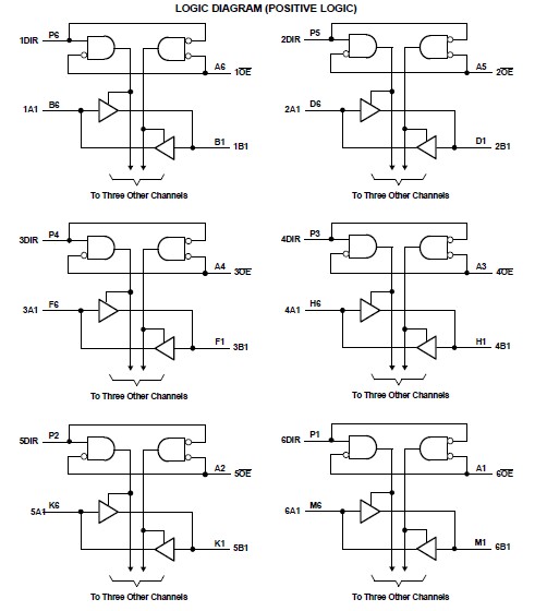
The SN74AVC24T245ZRGR is a 24-bit noninverting bus transceiver. It uses two separate configurable power-supply rails. The SN74AVC24T245ZRGR is optimized to operate with VCCA/VCCB set at 1.4 V to 3.6 V. It is operational with VCCA/VCCB as low as 1.2 V. The A port is designed to track VCCA. VCCA accepts any supply voltage from 1.2 V to 3.6 V. The B port is designed to track VCCB. VCCB accepts any supply voltage from 1.2 V to 3.6 V. This allows for universal low-voltage bidirectional translation between any of the 1.2-V, 1.5-V, 1.8-V, 2.5-V, and 3.3-V voltage nodes. The SN74AVC24T245ZRGR is designed for asynchronous communication between data buses. The device transmits data from the A bus to the B bus or from the B bus to the A bus, depending on the logic level at the direction-control (DIR) input. The output-enable (OE) input can be used to disable the outputs so the buses are effectively isolated.
Parametrics
SN74AVC24T245ZRGR absolute maximum ratings: (1)Supply voltage range: : –0.5 to 4.6 V; (2)Input voltge range(2)I/O ports (A port): –0.5 to 4.6 V; (3)Input voltge range(2)I/O ports (B port): -0.5 to 4.6 V; (4)Input voltge range(2)Control inputs: –0.5 to 4.6 V; (5)Voltage range applied to any output in the high-impedance or power-off state(2)A port: –0.5 to 4.6 V; (6)Voltage range applied to any output in the high-impedance or power-off state(2)B port –0.5 to 4.6 V; (7)Voltage range applied to any output in the high or low state(2)(3)A port –0.5 to VCCA + 0.5 V; (8)Voltage range applied to any output in the high or low state(2)(3)V B port: –0.5 to VCCB + 0.5 V; (9)Input clamp current VI < 0: –50 mA; (10)Output clamp current VO < 0: –50 mA; (11)Continuous output current: ±50 mA; (12)Continuous current through each VCCA, VCCB, and GND: ±100 mA; (13)Package thermal impedance(4)GRG/ZRG package: 50 °C/W; (14)Storage temperature range: –65 to 150 °C.
Features
SN74AVC24T245ZRGR features: (1)Control Inputs VIH/VIL Levels Are Referenced to VCCA Voltage; (2)VCC Isolation Feature – If Either VCC Input Is at GND, All Outputs Are in the High-Impedance State; (3)Overvoltage-Tolerant Inputs/Outputs Allow Mixed-Voltage-Mode Data Communications; (4)Fully Configurable Dual-Rail Design Allows Each Port to Operate Over Full 1.2-V to 3.6-V Power-Supply Range; (5)Ioff Supports Partial-Power-Down Mode Operation; (6)I/Os Are 4.6-V Tolerant; (7)Latch-Up Performance Exceeds 100 mA Per JESD 78, Class II; (8)ESD Protection Exceeds JESD 22 : 8000-V Human-Body Model (A114-A); 200-V Machine Model (A115-A); 1000-V Charged-Device Model (C101).
Diagrams

| Image | Part No | Mfg | Description |  |
Pricing (USD) |
Quantity | ||||||||||||
|---|---|---|---|---|---|---|---|---|---|---|---|---|---|---|---|---|---|---|
 |
 SN74AVC24T245ZRGR |
 Texas Instruments |
 Translation - Voltage Levels Low Power Low IOVdd Dual Channel |
 Data Sheet |

|
|
||||||||||||
| Image | Part No | Mfg | Description |  |
Pricing (USD) |
Quantity | ||||||||||||
 |
 SN7400 |
 Other |
 |
 Data Sheet |
 Negotiable |
|
||||||||||||
 |
 SN7400D |
 Texas Instruments |
 Gates (AND / NAND / OR / NOR) Quad 2-input Positive-NAND gates |
 Data Sheet |

|
|
||||||||||||
 |
 SN7400DE4 |
 Texas Instruments |
 Gates (AND / NAND / OR / NOR) Quad 2-input Positive-NAND gates |
 Data Sheet |

|
|
||||||||||||
 |
 SN7400DG4 |
 Texas Instruments |
 Gates (AND / NAND / OR / NOR) Quad 2-input Pos- NAND |
 Data Sheet |

|
|
||||||||||||
 |
 SN7400DR |
 |
 IC QUAD 2IN POS-NAND GATE 14SOIC |
 Data Sheet |
 Negotiable |
|
||||||||||||
 |
 SN7400DRE4 |
 |
 IC QUAD 2IN POS-NAND GATE 14SOIC |
 Data Sheet |
 Negotiable |
|
||||||||||||
 (Hong Kong)


