(Hong Kong)

Product Summary
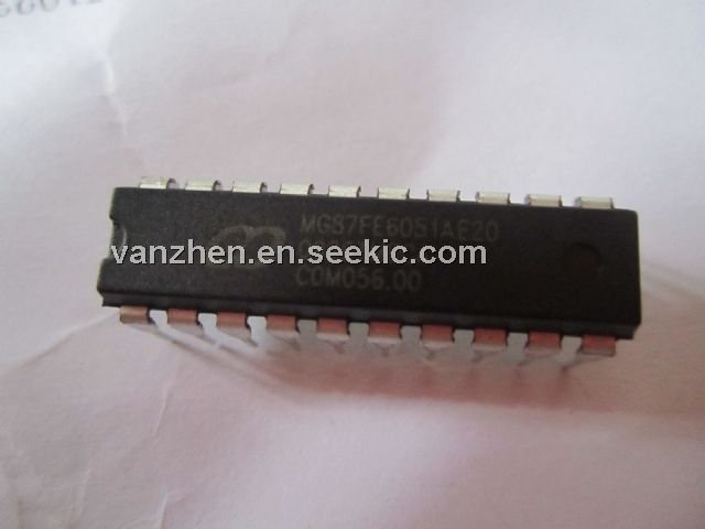
The MG87FE6051AE20 is a single-chip 8-bits microcontroller with the instruction sets fully compatible with industrial-standard 80C51 series microcontroller. 2K/4K/6K bytes flash memory and 256 bytes RAM has been embedded to provide widely field application. In-System-Programming and In-Application-Programming allows the users to download new code or data while the microcontroller sits in the application. The MG87FE6051AE20 executes one machine cycle in 6 clock cycles or 12 clock cycles. The MG87FE6051AE20 has one 8-bit I/O ports (P1), one 7-bit I/O port (P30~P35,P37), two 16-bit timer/counters, one PWM-timer for 8-channel PWM output, a seven-source, four-priority-level interrupt structure, an enhanced UART, a precision analog comparator, on-chip crystal oscillator(combined P42,P43) and a high-precision internal oscillator.
Parametrics
MG87FE6051AE20 absolute maximum ratings: (1)Ambient temperature under bias: -55 to +125℃; (2)Storage temperature -65 to + 150℃; (3)Voltage on any Port I/O Pin or RESET with respect to Ground: -0.5 to VDD + 0.5 V; (4)Voltage on VDD with respect to Ground: -0.5 to +6.0 V; (5)Maximum total current through VDD and Ground: 400 mA; (6)Maximum output current sunk by any Port pin: 40 mA.
Features
MG87FE6051AE20 features: (1)80C51 Central Processing Unit; (2)MG87FE/L2051 with 2KB flash ROM, 4051/4KB flash ROM; 6051/6KB flash ROM; (3)Operating voltage: E type: 4.5V~5.5V and L type: 2.4V~3.6V; (4)Operation frequency : 48MHz(max)@12T and 24MHz@6T mode; (5)ISP memory zone could be optioned as 0.5K/1KB/1.5KB~3.5KB; (6)IAP capability; 1KB IAP memory size; (7)On-chip 256 bytes data RAM for MG87FE/L2051/4051/6051; (8)Code protection for flash memory access; (9)Two 16-bit timer/counter; (10)PWM-Timer for PWM generator or normal 8-bit timer, selectable interrupt on INT3; (11)Seven sources, four-level-priority interrupt capability.; (12)Enhanced UART, provides frame-error detection and hardware address-recognition; (13)15 bits Watch-Dog-Timer with 8-bit pre-scalar, one-time enabled by CPU or power-on; (14)Power control: idle mode and power-down mode, Power-down can be woken-up by INT0(P3.2), INT1(P3.3), INT2(P4.3), INT3(P4.2) and other I/O.
Diagrams